Saturday 28 September 2019

Second junior CoderDojo starts this afternoon

Today sees a second weekly group of 10 junior CoderDojos start.

That takes to 20 the total number of young people in Shannon who are exploring and sharing their enthusiasm for computers.

That's fantastic!

For the newbies I'll be covering the basics of Scratch over the next few weeks and illustrating the many capabilities of that language using the Spacecraft.sb3 program :)

For the more experienced people I'll be encouraging them to progress their projects with a view to either them or me presenting their work at Xmas.


Sunday 4 August 2019

LoRa Compost temperature probe

Goal to create a LoRa based hot compost temperature probe capable of communication over a hundred meters to a Raspberry Pi computer.

To achieve this I plan to:
1) add a DS18B20 temperature/humidity probe to one of my two ESP32 LoRa modules
2) to connect the other one to my laptop.
3) to protect the probe from the 70 C temperatures


https://hackaday.io/project/27791-esp32-lora-oled-module
https://components101.com/sensors/ds18b20-temperature-sensor
https://create.arduino.cc/projecthub/TheGadgetBoy/ds18b20-digital-temperature-sensor-and-arduino-9cc806


(Sat 10/8/19 9:42am) Worked on it again last night and got it going!


I first got it going on a NodeMcu first to check the probe wiring was OK and it was great when it started to work once I shoved a wire in fully :)


The probe itself needs to take high temps > 80 C ? and be shoved 1 meter into a hot compostor for weeks on end. So I'm using plumbers QPL barrier pipe which is good to 92 C !


The NodeMCU code was based on the code at:
http://www.esp8266learning.com/wemos-mini-ds18b20-temperature-sensor-example.php and I used two 2.2K resistors in series to pull up D4 and I selected the board ""
nodeMcu_ds12b20_works_ok.ino (NOTE: "ds(33)" should be changed to "ds(D4)" in this code)

For the Heltec ESP32 LoRa board I first used the example code File > Examples > Heltec ESP32 Dev-Boards >  Factory Test > WiFi LoRa 32Factory Test and selected the board "Heltec WiFi LoRa 32(V2)" and then merged in the earlier
code resulting in the following program.
WiFi_LoRa_32FactoryTest_ds12b20_works_ok_1.ino


NOTE: I used pin 33 for the serial bus and selected it using the code:
   OneWire  ds(33);  // on pin D4 (a 4.7K resistor is necessary)

So now it works I need to refine it by:

On the Heltec probe side of things:
P1) to display temp in large font
P2) to be boxed with holes for probe and antenna sockets (all to be water proof so it can be left outside for a month)
P3) code to be made low power with one reading every 5 minutes (aim to have it last a month on same charge)
P4) add voltage monitor

On the Heltec receiver:

R1) Make it publish temps to MQTT broker

On the Node-Red
N1) have a page to monitor temp over a month
N2) Add e-mail alarms for low voltage, low temp and high temp! By publishing the Last Will and Testimony (LWT)


So let's address these one after the other :)

https://www.instructables.com/id/WiFi-Kit-32-NTP-Clock/ has an example of large fonts using the XXX library in its wifi_kit_32_ntp_clock.ino code.
#include                              <U8g2lib.h>                           // see https://github.com/olikraus/u8g2/wiki/u8g2reference
And installed library "U8g2 by Oliver" using Arduino IDE.

It should be good to go as was quoted on Heltec site: https://heltec.org/project/wifi-kit-32/

I choose the following display from the list at:
https://github.com/olikraus/u8g2/wiki/u8g2setupcpp


Had problems with LWT as MQTT broker would see a disconnect after 20 secs and publish it!

1565466723: New connection from 192.168.1.125 on port 1883.
1565466723: New client connected from 192.168.1.125 as esp8266-68:c6:3a:e9:f4:a-eb (c1, k15, u'inisfree').
1565466745: Client esp8266-68:c6:3a:e9:f4:a-eb has exceeded timeout, disconnecting.
1565466745: Socket error on client esp8266-68:c6:3a:e9:f4:a-eb, disconnecting.


So do I need to extend sockets timeouts on Rasp Pi ?


Thursday 4 July 2019

Had to get access to serial port with new 64-bit Ubuntu 18.04 OS

1
Your user account probably doesn't have permission to use the serial port.
Two ways to address this:
  • Easiest, but not advised: Run the Arduino IDE as root (eg launch from the command line using sudo).
  • The second, more advisable way to do it is to add your user to the dialout group, which has permission to use the serial port. Use the command sudo adduser $USER dialout. You will need to log out then log back in for it to take effect though (or try this). To list groups of current user use groups or id -Gn.
Once this is done, when you select the correct serial port (as others have mentioned maybe /dev/ttyUSB0) you should be able to write, allowing you to program the Arduino.

Saturday 22 June 2019

Installing Arduino IDE on Linux

https://askubuntu.com/questions/786367/setting-up-arduino-uno-ide-on-ubuntu

I found I couldn't download over serial port Blink example to NodeMCU

kilnageer@kilnageer-Inspiron-3537:~$ dmesg | grep tty
[    0.000000] console [tty0] enabled
[ 9640.093642] usb 1-1.4: ch341-uart converter now attached to ttyUSB0
[10666.992832] ch341-uart ttyUSB0: ch341-uart converter now disconnected from ttyUSB0


[10668.867323] usb 1-1.4: ch341-uart converter now attached to ttyUSB0
kilnageer@kilnageer-Inspiron-3537:~$ sudo adduser kilnageer dialout

Then logged out as Kilnageer and back in. Download then worked.

Had to include libraries PubSubClient for MQTT and adafruit unified sensor


https://lastminuteengineers.com/esp8266-dht11-dht22-web-server-tutorial/


http://www.steves-internet-guide.com/install-mosquitto-linux/

Installing The Mosquitto Broker

The download links and install directions for Linux are here.
I followed the install instructions for Ubuntu but they seemed to miss a few important steps. Here are the steps I used.
  • sudo apt-add-repository ppa:mosquitto-dev/mosquitto-ppa
  • sudo apt-get update
  • sudo apt-get install mosquitto
  • sudo apt-get install mosquitto-clients 

kilnageer@kilnageer-Inspiron-3537:~$ mosquitto_sub -h 192.168.1.100 -t \esp8266_2_arduino_out
{"micros":22966832,"counter":4}
{"micros":28040128,"counter":5}


Trouble with DHT22 though DHT11 works. May use code here to investigate:
https://www.keuwl.com/electronics/rduino/bluet/08-dht11/

Rather than Adafruit uni sensor library for DHTXX.

Also .cpp code available from here:
https://www.instructables.com/id/How-to-interface-Humidity-and-Temperature-DTH11-Se/
https://drive.google.com/file/d/0B1paTI5fzcHodno5azFOSVVDT0E/view?usp=sharing


Saturday 15 June 2019

Installing Arduino IDE on Ubuntu Linux laptop

I went to https://www.arduino.cc/en/Main/Software

and then clicked on the Linux 64-bit download link

I then saved the arduino-1.8.9-linux64.tar.xz file to my downloads directory

kilnageer@kilnageer-Inspiron-3537:~/Downloads/arduino-1.8.9$ sudo ./install.sh
(which will set up a menu item for Arduino, etc.)

Can now see "Arduino IDE" under "Programming" menu item.

But it doesn't do anything..
Trying manually..
kilnageer@kilnageer-Inspiron-3537:~/Downloads/arduino-1.8.9$ ./arduino
./arduino: line 35: /home/kilnageer/Downloads/arduino-1.8.9/java/bin/java: cannot execute binary file: Exec format error

kilnageer@kilnageer-Inspiron-3537:~/Downloads/arduino-1.8.9$ java -version
openjdk version "11.0.3" 2019-04-16
OpenJDK Runtime Environment (build 11.0.3+7-Ubuntu-1ubuntu218.04.1)
OpenJDK Server VM (build 11.0.3+7-Ubuntu-1ubuntu218.04.1, mixed mode, sharing)

All due to having a 32-bit Ubuntu installed! "uname -m" reports this as "i686" rather than "x86_64"

Saturday 8 June 2019

Getting NodeMCU working again...

In order to demonstrate these at the Senior CoderDojo I fired up the:

1) ESPlorer.jar IDE for NodeMCU.

switched to using Adruino IDE

https://www.instructables.com/id/Programming-ESP8266-ESP-12E-NodeMCU-Using-Arduino-/

In Adruino Preferences, Additional Board Managers URLs box enter
http://arduino.esp8266.com/stable/package_esp8266com_index.json,https://dl.espressif.com/dl/package_esp32_index.json

and then update button in Tools > Board Manger (search for 8266)

Should then be able to select the 8266 board > "Node MCU 1.0 (ESP-12E Module)"

Worked briefly until it flashed device!


#define LedPin D0

// the setup function runs once when you press reset or power the board
void setup() {
  // initialize digital pin LED_BUILTIN as an output.
  pinMode(LedPin, OUTPUT);
}

// the loop function runs over and over again forever
void loop() {
  digitalWrite(LedPin, HIGH);   // turn the LED on (HIGH is the voltage level)
  delay(1000);                       // wait for a second
  digitalWrite(LedPin, LOW);    // turn the LED off by making the voltage LOW
  delay(1000);                       // wait for a second
}


Sketch uses 257712 bytes (24%) of program storage space. Maximum is 1044464 bytes.
Global variables use 26572 bytes (32%) of dynamic memory, leaving 55348 bytes for local variables. Maximum is 81920 bytes.
esptool.py v2.6
2.6
esptool.py v2.6
Serial port COM10
Connecting....
Chip is ESP8266EX
Features: WiFi
MAC: ec:fa:bc:28:71:df
Uploading stub...
Running stub...
Stub running...
Configuring flash size...
Auto-detected Flash size: 4MB
Compressed 261872 bytes to 191272...

Writing at 0x00000000... (8 %)
Writing at 0x00004000... (16 %)
Writing at 0x00008000... (25 %)
Writing at 0x0000c000... (33 %)
Writing at 0x00010000... (41 %)
Writing at 0x00014000... (50 %)
Writing at 0x00018000... (58 %)
Writing at 0x0001c000... (66 %)
Writing at 0x00020000... (75 %)
Writing at 0x00024000... (83 %)
Writing at 0x00028000... (91 %)
Writing at 0x0002c000... (100 %)
Wrote 261872 bytes (191272 compressed) at 0x00000000 in 16.9 seconds (effective 124.2 kbit/s)...
Hash of data verified.

Leaving...
Hard resetting via RTS pin...


You need to press RST button on board to run the program..

These projects saved to C:\Users\kilnageer\Documents\CoderDojo\2018 Reboot\NodeMcu on my laptop along with screenshots.

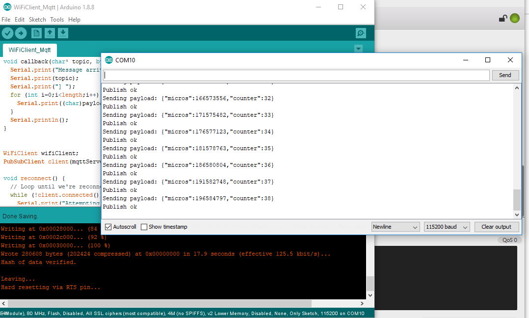
Next tried the WifiClient example and got:

Connecting to vodafone-2124
.....
WiFi connected
IP address:
192.168.1.115
connecting to djxmmx.net:17
sending data to server
receiving from remote server
"When a stupid man is doing something he is ashamed of, he always declares
 that it is his duty." George Bernard Shaw (1856-1950)


So all working great next to add DHT11 sensor code and MQTT client publishing!

MQTT worked great! Checked using MQTT FX app on laptop


Next to DHT11/22 code..

15.7/15.9 C at 12:25pm

1. Open your Arduino IDE and go to Sketch Include Library > Manage Libraries. The Library Manager should open.
2. Search for “DHT” on the Search box and install the DHT library from Adafruit.


Getting ShrimpKit working again..

The ShrimpKit are great single chip based prototyping kits that can be programmed using the Adruino IDE.

http://start.shrimping.it/kit/shrimp.html


I started using them years ago in CoderDojo and then stuffed them in boxes. So they all need a bit of TLC to get their flashing LED projects working again for the Senior CoderDojo in Shannon Library this afternoon :)

First lets check the wiring. By step through these pages and comparing to the boards actual wiring.
http://start.shrimping.it/project/blink/build.html

Also ensure Adruino IDE is setup correctly:
http://start.shrimping.it/project/shrimp/program.html

Steps to get control of them!
1) Launch Adruino 1.8.8 IDE.
(Hah! As soon as I plugged one it it started to transmit "helo world" endlessly to the laptop stopping me from doing anything else!)
2) Select: Tools > Boards -> "Adruino/Genuino Uno"
3) Open the Flashing LED example project: File > Examples > 01.Basics > Blink
4) Plug in the Shrimp Kit into a USB port and select its COM port (e.g. COM6 check using Device Manager)
5) Compile and download the Blink sketch program to the Shrimp kit: Sketch > Upload (or hit Ctrl-U)
6) The red LED should now be blinking! :)

Got two breadboards working at the library.


Friday 7 June 2019

LoRa WiFi Testing got as far as 400m across Shannon Town

Received my two LoRa OLED transceivers today and I'm now working through the project at:
https://hackaday.io/project/26991-esp32-board-wifi-lora-32


My aim is to send messages between the two boards over a 1km line of sight.

So fired up the Adruino 1.8.8 IDE on my Windows 10 laptop and selected Sketch > Include Library > Manage Libraries and search for “Wifi_LoRa_32“. Selected the "Heltec ESP32 Dev-Boards"  and installed it.
https://github.com/HelTecAutomation/Heltec_ESP32

After this I could Tools >

Downloaded ESP32-DrawLogo.ino to C:\Users\kilnageer\Documents\Arduino and loaded it.

But found that they transceiver test code in already so can test as soon as powered up! :)

https://randomnerdtutorials.com/installing-the-esp32-board-in-arduino-ide-windows-instructions/

Once "esp32" by Expessif Systems installed under Boards Manager

Wow! Built-in firmware works fine!


Just powered by laptop USB ports. Then moved one transceiver as far as the library (400m) still worked! That's from inside one building to inside another building across a town! So with a roof mounted antenna at home and the other transceiver at the allotment (1500m) it might still just work.


Successfully download WiFi_LoRa_32FactoryTest sketch and works the same as the shipped firmware. Happy days :)

Can park this up for now then.

Monday 27 May 2019

Senior CoderDojo started

I started a seniors CoderDojo last Saturday in the library from 12 noon to 1 pm. This is for up to five  13 year olds and over to teach them about Adruino based electronics. They will need their own laptops.

No one has signed up yet but it is early days and I'm looking forward to letting people loose on my box for 37 sensors! :)


It's also giving me an opportunity to package up some of my electronics (Rasp Pi, NodeMCU. Shrimp kit, etc.)


Friday 26 April 2019

Lottery Scratch program

Here's some screen shots of the lottery Scratch program I wrote a few weeks ago to decide who uses the Micro:bit kits :)

Enjoy.


Friday 5 April 2019

Trying out the Kitronik Inventor's Kit for the BBCMicro:bit

Assembled base board and added a Micro:bit then did Experiment 1 on p 14 of the manual.
Button A displays a :) smiley face and button two displays "Hello World!". These are then jumpered to external buttons.

All OK. (I hadn't realised I only needed the battery pack for standalone mode!)


Thursday 4 April 2019

Just tested an Inky Phat for a Raspberry Pi Zero W. Magic!

Great quality display even with the power off!
https://learn.pimoroni.com/tutorial/sandyj/getting-started-with-inky-phat

Currently I need to enable SPI and I2C using "sudo raspi-config" beforehand.


Just finished assembling the :MOVE mini for the BBC Micro:bit. Great fun :)

Just finished assembling the :MOVE mini for the BBC Micro:bit. Great fun :)

Sadly to trim the servo motors (which can start to move by themselves you have to dismantle the whole unit to get at the screws to do it). But should be great fun to use as a chart plotter, etc.


Saturday 23 February 2019

We are now in our 5th and final week of the Shannon CoderDojo reboot.

And I continue to be very impressed with the enthusiasm and progress made by all 5 ninjas.

Currently, three are working on their Better than FIFA soccer game and two are working on their colour puzzle solving game called the Mixing Game.

Today we need to decide where to go next. As I see it there are three broad options:

1) Continue as we are with 5 ninjas working on their projects until these are completed.

2) Expand the club by taking on 5 new ninjas but I will be relying on the existing ninjas to help the newbies

3) Keep the same club size and introduce a new skill. Such as web page design (based on the excellent book the library has been given called CoderDojo: Create with Code)

I'll ask the ninjas what they think at the end of this session.

Saturday 16 February 2019

This was the four session and the time for the ninjas to go solo with their own projects! :)

I was very pleased how they formed into two groups (of two and three) and decided on their projects and roles within these projects. We did this by each ninja stating a couple of their interests and this naturally split the club into two groups: sport and science.

The first Scratch project is a soccer game called Better Than FIFA and each ninja is working on different aspects of the game (sprites/costumes, backdrops, game play, etc.)

The second project is a puzzle solving game where the player gets to the next level after solving a puzzle. the first puzzle is based on colours. Its called the Mixing Game.


Saturday 9 February 2019

This is the third session and where I finish introducing the programming tools available in Scratch.

The idea being that further learning is based around projects the ninjas will create.

So I used the Spaceship Supply program to illustrate the following concepts:
- Blocks (user definable chunks of code)
- Messages (so that the Spaceship knows when it has been touched by the supplies)
..


Saturday 2 February 2019

In the second session today I shared a Scratch Spaceship Supply program and how you can customise your own sprites and backdrops. (by downloading from the web and rescaling)

This is a complicated multi-sprite Scratch game where the player must steer the supplies from the supply ship at the bottom of the screen to to the spaceship which zooms past at the top of the screen.

The code can then by used as a reference for various things the ninjas may want to achieve in their own Scratch programs.

Such as:
1) Controlling a sprite (the supply ship by using the left/right arrows)
2) Changing the sprite costumes (the spaceship smiles when it gets its supplies)
3) Synchronizing sprites (the supplies follow the horizontal position of the supply ship)
4) Moving sprites automatically (the supplies move upwards when the player presses the spacebar)
5) Communication between sprites (the supplies tell the space ship when they have arrived)
6) Keeping sprites on screen (boundary checking for x and y)

I then asked the ninjas to delete the spaceship and supplies sprites and just spoke about how the player controls the supply ship

I also demonstrated the BBC Micro:bit playing Scissors, Stone and Paper.
https://microbit.org/

Saturday 26 January 2019

In the first session of the Shannon CoderDojo reboot I explained the basics of Scratch and gave out stickers, badges and USB bracelets I received from CoderDojo HQ.

I was very impressed on how quickly all the ninjas took to Scratch and started experimenting with the code blocks.

Here are some useful links that are also on the USB bracelet:

Older Scratch projects